MAGNETIC SUSPENSION BACK
RESTORING FORCE
Since the invention of the moving coil loudspeaker one of the major problems has been to get the moving coil with
cone, surround and spider attached back to its starting position rapidly after an electrical signal has driven it out.
More precisely, return the moving mass with no overshoot! In the past, attempts have been made using the air
compression in a sealed enclosure behind the speaker diaphragm. Whether it is isothermal or adiabatic compression
of air the results are too slow. Driver manufacturers have also designed spiders and surrounds to act as a spring to
aid in the movement of the cone assembly.
A moving coil loudspeaker reproduces sound as a result of an electrical signal flowing in a coil in a magnetic field,
which causes the coil to move in the field carrying the diaphragm with it, the direction being determined by the
polarity of the signal. The signals are generally derived from two basic forms: a single d.c. transient which pushes
in one direction only; and the sine wave which pushes in two directions alternately. In musical sounds you get both
and infinite combinations of them.
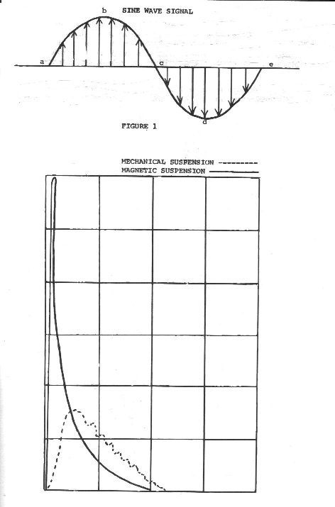
Fig. 1 shows a representation of a simple sine wave. The arrows symbolize the electrical signal pushing on the coil
and speaker cone, first in one way and then the other. The length of the arrows represents the push on the coil and
cone. From point a to point b the amount of push is increasing and from b to c it lessens to zero, then it turns around
and does the same thing over in the opposite direction. Now from b to c and from d to e as the arrows get shorter and
the push lessens, something has to move the coil and cone backward, which is what is called the "restoring force". What
does the restoring force have to do? Looking at Fig. 1 again, the distance from point a to point e is time. At 50cps it is
1/50th of a second. Therefore, the restoring force must be able to move the coil and cone from point b to point c in 1/4
of that time or 1/200th of a second. The motional velocity of the cone will depend on the frequency and the distance the
cone travels on its amplitude. Since the loudspeaker is a velocity device, to maintain constant acoustical power output,
the excursion of the cone must vary as the inverse square of the frequency. At 25cps, although the frequency has been
cut in half, the amplitude or excursion has to quadruple. So although the cone has to move from b to c in only 1/100th
of a second, it has to go four times as far....its motional speed must be doubled.
The above data would seem to indicate that the restoring force would not be so important at the higher frequencies
because amplitude varying by squares would be in reverse direction, so motional speed would be going down.
Unfortunately, when the frequency goes up, the matter of inertia becomes a question. At 3000cps the electrical signal
has to start up a mass, the coil and cone, from no velocity and get it out to its stopping point in a split second. The
restoring force has to bring it to a dead stop and start it in the opposite direction and stop it at the starting point. This
situation worsens with increasing frequency. It has been calculated that at 60cps with a cone excursion of 1/4 inch, the
forces involved are around 93 times the acceleration of gravity, and at 10,000cps it is up around 2060 g's. With a large
magnet, this "g" element can be overcome but getting it back is another matter.
Why is this restoration speed essential? Since the outward thrust is extremely rapid (due to the magnetic action of the
coil and magnet), by the time the coil has begun to return to its starting position, the next signal is ready to perform
work; on the other hand, a voice coil which is never back in time to take full advantage of it. But we are speaking of
only a simple signal. What happens when the voice coil has to deal with complex signals or transients which are so
important for achieving natural sound? The problem becomes infinitely greater.
We ran some experiments with a conventional coil to see how fast the restoring force would make it move. Pulling the
coil to full amplitude with a strong light thread, then connecting the coil to an 8 ohm load to match it and placing an
oscilloscope across same for observation, we burned through the thread and noted that the coil moved about 1/4 inch
in 1/350th of a second. That is fairly fast and this speed can be kept up to about 90 cps, but once we get much above
that, the coil starts lagging behind the signal considerably. Next we used a d.c. transient at 10 cps and it was possible
by utilizing the oscilloscope and expanding the sweep frequency to 100 cps to determine the time required for the
voltage to rise to its maximum point. It was 1/1300th of a second! To reproduce this signal the coil must move out to
maximum excursion in 1/1300th of a second, be stopped and moved back in 1/1300th of a second. With this coil moving
at best in 1/350th per second, this was obviously an impossibility.
From this simple experiment, a logical question arises: If the magnetic thrust is faster than the mechanical restoration
force, why not employ magnetic restoration? This is exactly what Dr. Harold Luth, Chief Engineer of the Hartley
Products Corp. evolved and patented under the name of Magnetic Suspension. It was mentioned earlier that a fixed
magnet helps thrust the voice coil outward. In the Hartley-Luth Magnetic Suspension speakers, this same magnet is
used to return the coil back to its neutral position. This is accomplished quite uniquely as follows: A thin film of iron,
backed by a thin strip of plastic, is placed around the coil form beneath the coil winding. The geometry of the film is
very carefully adjusted for maximum axial force, in both positive and negative directions. Because there is no
mechanical suspension (in the form of a spider or accordion pleated concentric disc), the voice coil with its iron band
rests at a neutral point within the magnetic field of the fixed magnet. From this position, it resists motion in either
direction. Because the fixed magnet is quite powerful, to move the coil and cone from this "rest" position to the
maximum outward thrust would require a force of nearly two pounds. But this would be true only if we used a
mechanical force. Here we have a magnetic force generated by the coil and aided by the force of the fixed magnet.
Another simple but elegant solution.
Previously discussed was the speed of a conventional coil suspension and it was found to move from its maximum
excursion to its rest position in 1/350th of a second. By a similar method, Dr. Luth determined the speed of Magnetic
Suspension to be 1/1600th of a second. This is truly fast, but there were other interesting observations. In Fig. 2, the
traces noted on the oscilloscope of the conventional coil and the Magnetic Suspension coil are super-imposed. On the
solid line curve for the MS coil, the voltage collapse curve pretty much follows that normally obtained in a inductor.
But in the dotted curve for the mechanical suspension, the voltage collapse curve contains a number of intermediate
peaks. In an amplifier this would probably be called ringing; in loudspeakers it's usually called hangover, but in any
event it is the result of the mechanical spring bouncing.
This magnetic spring is an engineer's delight. It is non-mechanical, it never changes, it never fatigues, and is unaffected
by temperature changes. What's more, it doesn't bounce! When the coil moves to its maximum excursion and is
released, it flies back to its neutral position and stops exactly at dead center. There is no overshoot and the action is
linear.
It has been emphasized that one of the great barriers to faithful reproduction of sound is a sluggish voice coil. We also
know that a pure unadorned sine wave signal is rarely encountered. With the voice coil now in a position to perform
with lightning speed, the results are translated into superlative transient response. It is this quality of magnetic suspen-
sion which makes it possible to convey every nuance within the kaleidoscopic spectrum of music.
Fig. 1
FIG.2
THE EQUALIZED FLUX MODULE
( EFM )
From the beginning, it has been evident that speaker magnets are structurally asymmetric......and it follows that the
magnetic field in the structure is asymmetric. Conventionally, we speak of "the lines in the gap". The magnetic lines
of force above and below the top plate of the magnet were always unknown for the very good reason that no practical
way was available to measure them.
A common method of measuring the magnetic field in a speaker magnet utilizes a search coil connected to a ballistic
galvanometer. The coil is placed in the gap and quickly pulled out of the gap, thus the turns of wire in the coil cut the
magnetic lines of force generated, and the electrical current is measured with the galvanometer. Unfortunately, this
measures the average field in the gap. You cannot pin-point the lines.
Magnetic lines are defined in gravimetric units, which is to say, force equals mass times acceleration (of gravity). With
this basic physical law as a starting point, Dr. Luth designed an instrument with a coil whose length was measured in
thousandths of an inch, which we could place in a precise point in the gap. A current passing through the coil generated
a force which was balanced with a fixed mass. We measured the field in terms of its definition - an absolute value.
The next step was to design a dynamic search coil, in which a single turn of wire five thousandths of an inch in diameter
could be set at any place in the gap and at any point above or below the gap. This coil is then vibrated at a very high
velocity with an amplitude of motion less than one ten-thousandths of an inch. The voltage generated in the single turn
is amplified and measured on a cathode ray tube, and calibrated against the gravimetric balance.
Using our new measuring instrument, we found that the magnetic field in all magnets was indeed asymmetrical.
Contrary to what one might expect in looking at the structure of the magnet, there were many more lines above the top
plate than below. With such a structure, there is no way to get an absolute uniform forward and backward motion of the
speaker cone. Amplitude distortion is inevitable.
Our new EQUALIZED FLUX MODULE is a totally balanced magnet, precise tooling and design, providing mirror
imaging of the magnetic field above and below the top plate of the magnetic assembly. The results are a more efficient
gap, and the elimination of amplitude distortion.